5.20 CONSTRUCTION WORK ZONE TRAFFIC CONTROL
5.21 TRAFFIC CONTROL SPECIFICATION REFERENCES
Contract documents include references to traffic control requirements in many locations. Project plans contain references to traffic control requirements in the traffic control plan tabulation usually found on plan sheet J.1. Plans may also contain project specific traffic control and/or staging details. An extensive list of information sources regarding traffic control is found in Appendix 5-8.
Traffic control requirements may also be found in the specifications for specific construction activity.
ATSSA Quality Guidelines for Temporary Traffic Control Devices and Features
The American Traffic Safety Services Association (ATSSA) “Quality Guidelines for Temporary Traffic Control Devices and Features” is intended to be used by field personnel to help them inspect the work zones. The guide is a de-facto national industry standard to determine an acceptable quality level for a typical work zone traffic control device. The guide includes examples of acceptable, marginal, and unacceptable work zone traffic control devices. It is intended to further define the language in the Manual on Uniform Traffic Control Devices which requires that "devices used are clearly visible, clean, and in good repair."
To order additional copies of the “Quality Guidelines for Temporary Traffic Control Devices and Features”, contact the American Traffic Safety Services Association.
Oversized Loads in Work Zones
Work zones often change the space available to an oversized load to pass through. These restrictions should be identified in the 511 Travel Restrictions tabulation typically located within the J-sheets of the construction plans. However, it is important to understand where these restrictions come from and how they should be reported. A guide has been created that covers the reporting of restrictions within work zones as well as the background and several special cases. This guide can be found in the Work Zone Reference Library https://iowadot.gov/workzonereferencelibrary
5.22 TRAFFIC CONTROL EVALUATION AND CHANGES
Specification 2528.03, O, states that traffic control changes cannot be made without concurrence by the RCE Office. Field flexibility is often necessary due to situations that do not fit standard traffic control layouts such as hilly terrain, overhead power lines or side roads, and entrances that may impact the location of temporary traffic control signs and devices. Presence of unusual traffic generators or high turning movements, at a specific location, may also require traffic control adjustments.
In order to minimize the potential for traffic control changes, evaluate construction work zones prior to installation of traffic control signing, and again when operational, to look for any problem areas that may affect operational quality. Early review of proposed traffic control signing situations prior to the preconstruction conference will allow traffic control detail changes to be made before public traffic is impacted. During construction operations, traffic control evaluations should be held during work hours, on weekends, and also at night. Presence of skid marks is a good indication of a problem area.
Oftentimes, it is difficult to determine appropriate traffic control improvements to respond to traffic handling problems on projects. Appendix 5-9 discusses possible traffic control problems and potential solutions to these problems.
The Construction and Materials Bureau is available to help evaluate traffic control changes in conjunction with RCE Office staff to ensure uniformity statewide and to help provide a perspective on what has been successful for similar problems in the past.
In order to allow for field uniformity for effective decision making relating to traffic control changes, the following paragraphs can be used to help determine appropriate traffic control changes:
Make immediate changes when obvious operational problems exist. For other than obvious operational problems that could be dangerous to motorists or workers, contact the Construction and Materials Bureau first for help in determining appropriate changes.
The following modifications to traffic control details should not be made:
· Do not reduce the number of traffic control signs
· Do not change taper lengths
· Do not change the sign word message or symbol
· Do not change the sign color combination
· Do not reduce sign size or alter sign shape
Field adjustments can be made in the following areas without RCE Office notification:
· Individual sign locations may be adjusted up to a maximum of 100 feet as long as no two signs, either permanent or temporary, become closer than 100 feet apart. Removal, covering, or adjusting of permanent signs in the vicinity of construction work zones should be coordinated with the area maintenance manager (AMM).
· Paired signs may be adjusted a maximum of 100 feet.
· Taper location, arrow display location, and corresponding lane merge signs may be adjusted up to 500 feet further away from the construction work area. This is appropriate with poor advance sight distance due to hills or curves, or when earlier detection of the arrow display is needed.
All traffic control changes, or revisions should be documented.
5.23 CONSTRUCTION ZONE CRASH REPORTING
If an Iowa State Patrol officer determines the Iowa DOT needs to make immediate repairs at a construction work zone crash site, the investigating officer will contact the nearest Iowa State Patrol communication base station. They will notify the local maintenance area supervisor who will assess damage to Iowa DOT facilities and take necessary action. The area supervisor will contact the RCE if construction work zone traffic control devices or other items are damaged. The RCE will inform the contractor representative of needed corrective action. When construction work zone crash site does not require immediate corrective action by DOT or contractor representatives, the investigating officer is to report the crash to the RCE within 12 hours.
Investigation Procedure
For crashes resulting in property damage to Iowa DOT facilities, the RCE should identify repair costs. When public traffic is maintained through a project, the Operations and Finance Administration will be responsible for recovering damages from motorists on work that is essentially complete and acceptable. An example is damage to new guardrail on a staged bridge construction. The RCE should identify work status when submitting investigative report. Repair costs and supporting documentation should be submitted on Form 181310 "Memorandum Cost Report." An approved contract modification can be attached to Form 181310 to document costs in lieu of completing that part of the form.
Crash Notification Procedure
Inspection or contractor staff should report construction work zone crashes to appropriate enforcement authorities (usually Iowa State Patrol for rural Iowa DOT administered projects) and notify appropriate medical responders if needed. Inspection supervisory staff, contractor supervisory staff, and the Traffic Management Center should be notified promptly. Note additional reporting procedures for severe personal injury or fatality crashes.
Reporting of Severe Personal Injury and Fatal Crashes
If a crash results in a severe personal injury or fatality within an Iowa DOT administered construction work zone, immediately notify the Construction and Materials Bureau, Highway Administration Chief Engineer, Operations Bureau Director, Strategic Communications & Policy Bureau, District Engineer, District Construction Engineer, and Traffic Management Center.
Additional information to be gathered and forwarded by email within one working day to the Highway Administration Chief Engineer, Operations Bureau Director, Construction and Materials Bureau, Strategic Communications & Policy Bureau, Claims Manager, Finance Bureau, District Engineer, District Construction Engineer, and Traffic Management Center includes:
· Project Number
· County
· Route Number
· Direction
· Milepost
· Date of Crash
· Time of Crash
· Contractor
· Traffic Control Required in the Contract Documents
· Approved Traffic Control Modifications
· Brief Description of Facts Surrounding Crash
(Do not include hearsay, assumptions, or unsubstantiated facts.)
A sample format is included in Appendix 5-5.
Incident Reporting by Contractors
The bid item Monitoring with Incident Response, defined in Specification Article 2528.01, B requires contractors to report any construction work zone incidents on forms provided by project engineer. A sample form is included in Appendix 5-2.
5.24 STOP SIGNS ON CONSTRUCTION PROJECTS
Particularly during grading activities, the need arises to frequently move stop signs as intersections are staged to allow access into project corridor. Instructions regarding the placement of stop signs during grading activity are as follows (See Appendix 5-3 for details on stop sign location.):
· Existing stop signs should be left in place until work in that area necessitates removal. If an intersection does not have an existing stop sign, the appropriate area maintenance manager (AMM) should be notified to install a stop sign immediately. All side roads to primary highways must have a stop sign unless the side road is physically closed.
· At the time work progresses to the point that the existing stop sign is no longer in the proper location or in the way of construction activities, the stop sign should be removed by the Iowa DOT Maintenance staff. A temporary stop sign, with a minimum size of 30 inch x 30 inch, should be furnished through the AMM and placed by the contractor. A temporary stop sign should be mounted approximately 5 feet high on a 4 feet Type III barricade furnished by the contractor. See drawing in Appendix 5-3. This sign may be moved as needed to allow construction to proceed but must be maintained in an effective position at all times traffic is staged through the intersection.
· When work at the intersection is completed to the point where the permanent stop sign can be installed, the Maintenance supervisor should be notified to install the permanent stop sign. This notification should be given on an intersection by intersection basis and not delayed until entire project is completed.
5.25 “ROAD WORK AHEAD" AND "END ROAD WORK" SIGNS
Specification 1107.09, A, 2, requires contractors to place "Road Work Ahead" (W20-1) and "End Road Work" (G20-2) signs at appropriate ends of highway construction projects. These signs need to be placed at all traffic control zones within a project to identify the start and finish of individual construction work areas. On any mainline roadway where a "Road Work Ahead" sign is placed, the opposite end of the work areas shall have an "End Road Work" sign placed.
Specification 1107.09, A, 2 requires that all "END ROAD WORK" signs be placed separately 500 feet beyond the work area. Separately mounting these signs requires that they be made to the correct dimensions, i.e. 60 inches x 24 inches.
The last paragraph of Specification 2528.03, A, 13 states that the “END ROAD WORK” signs may be eliminated for mobile or short duration (less than 1 hour) temporary traffic control zones. This specification DOES NOT allow the “END ROAD WORK” signs to be eliminated from any other type of temporary traffic control zone.
5.26 NO PASSING ZONES ON CONSTRUCTION PROJECTS
Often it is necessary to place temporary no-passing zones through a traffic control zone. Guidelines to aid in proper use of no-passing zones follow:
· Never shorten an existing no-passing zone for temporary traffic control.
· If existing no-passing zone is lengthened, a black on orange "No Passing Zone" (W14-3) sign should be erected at beginning of no-passing zone and existing black on yellow "No Passing Zone" (W14-3) sign should be removed or covered.
· If a temporary no-passing zone falls within an existing no-passing zone, no additional signs should be added. Either the existing black on yellow "No Passing Zone" sign may remain or be replaced with a black on orange "No Passing Zone" sign.
· If a no-passing zone ends within 400 feet of beginning of existing no-passing zone, then both no-passing zones should be connected to make one continuous no-passing zone. Only one "No Passing Zone" sign should be placed at the beginning of a continuous no-passing zone.
· Only one type [(black on orange) or (black on yellow)] of "No Passing Zone" sign should be used or visible to the motorist at any time.
5.27 CONTRACTOR ACCESS AND EQUIPMENT AND MATERIAL STORAGE
Contractor Access
Contractor access (ingress and egress) is becoming more important as traffic volumes increase on the highway system. Poor access locations could create traffic flow problems and potential safety issues for public traffic. Contractor access locations also could impact the constructability of the project, if access points are not logically thought out during the design and construction of a project.
The project designer needs to address how the contractor will safely move materials and equipment into the work area with minimal disruption to public traffic. This is a particularly critical issue on high speed / high volume highways such as Interstate highways and freeways, especially if temporary barrier rail is used to protect work areas.
If project plans do not include adequate contractor access details, the following items should be considered in determining appropriate contractor access locations:
· Anticipate types of work zones that typically create access problems. Examples are workspaces requiring work vehicles to merge into high-speed traffic and work activities that will generate frequent delivery of materials such as paving projects, bridge projects, and the delivery/movement of fill materials.
· Adequate acceleration/deceleration space for work vehicles should be provided.
· The location of access openings should provide adequate sight distance for both the contractor’s vehicles and public motorists. In extreme conditions, lane closures may need to be considered.
· Contractor access openings in temporary barrier rail should be treated with crash cushions to ensure that blunt ends of the barrier rail are properly protected. Any protected barrier rail openings should be located so they will not create a sight distance problem for equipment operators or motorists.
· High volumes of material haul vehicles may justify lowering the work zone regulatory speed limit per Construction Manual Section 5.42 “Temporary Work Zone Speed Limits”.
· Standard Road Plan TC-273 or a modification to this TC may be appropriate to place at contractor access locations. All warning signs for contractor access locations should be covered or removed when the access location is not in use, such as during weekends or nonworking hours.
Contractor access locations used during night time operations should be properly illuminated per the Night Time Lighting requirements included in Specification Section 2550.
Contractor access on Primary and Interstate highways also needs to follow requirements discussed in Construction Manual Section 3.71.
Equipment and Material Storage
When maintaining through traffic on construction projects, equipment and materials stored within the right-of-way during non-working hours should normally be stockpiled as far as possible from the traveled way. Unattended parked contractor and private vehicles should also be located as far as possible from the traveled way. Parking of private vehicles on Interstate right-of-way will be allowed in accordance with 2528.03, O, 12. Avoid storage areas in the following locations unless protected by temporary concrete barrier rail or metal beam guardrail:
· Within 15 feet of traveled way on undivided primary highways
· Within 50 feet of traveled way on divided highways
· On fore slopes
· On outside of sharp horizontal curves
Other storage locations may be approved by the project engineer when it is not practical to satisfy the above criteria. The project engineer should refer to Standard Road Plans TC-202 or TC-402 and Specification 1107.08, G when selecting alternate storage areas.
Storage behind guardrail must provide for partial collapse of rail upon impact. For beam guardrail, this is normally a minimum of 4.5 feet on parallel sections of rail (Standard Road Plan BA-200). A minimum of 8 feet should be allowed behind high tension cable guardrail (Standard Road Plan BA-351).
5.28 CONSTRUCTION WORK ZONE SIGNING DURING WINTER SHUTDOWN
Responsibilities of the resident construction engineer (RCE), district operations manager (DOM), and contractor for highway projects not fully completed by winter shutdown are reviewed below.
Unless contract documents identify signing responsibilities different than stated herein, the following guidelines will apply. Unusual circumstances will be handled on a project specific basis with approval of the Construction and Materials Bureau.
Uncompleted Projects
This category of projects includes contracts having some carry-over work into the next year or intended by plan to be multi-year contracts.
· Prior to winter shutdown, the RCE and DOM should field review the project to identify access, signing, and safety features needing completion before the contractor suspends work. The RCE and DOM will decide which items are the contractor’s responsibilities and what is best accomplished by Iowa DOT Maintenance staff. Cost of traffic control devices furnished by Iowa DOT Maintenance staff can be charged against the project.
· During the winter shutdown period, traffic operation services become the responsibility of the DOM according to Specification 1107.09, A, 1, g. This includes routine surveillance and sign maintenance.
· Snow removal for through traffic and local access, if needed, is the responsibility of the AMM.
Multi-Contract Projects
Some projects are phased so a series of contracts are awarded over several years. The most common examples are separate grading and paving projects. Unless contract documents identify responsibility for traffic signing between completion of one project and start of the next, the DOM is responsible for traffic services. The RCE and DOM should evaluate how to best resolve each specific situation. Options include:
· Maintenance staff installing and maintaining appropriate traffic control devices
· Purchasing or renting traffic control devices from contractor by contract modification
The district construction engineer (DCE) should address special needs in the contract documents.
Special Concerns
When temporary traffic signals are involved, the RCE should arrange, through the contractor, for emergency maintenance services. For routine winter maintenance, no payment will be made to contractor.
On urban projects, the RCE and DOM need to coordinate with the city on who is responsible for access, signing, and safety features.
5.29 FLAGGERS & PILOT CARS
Bid Item
Many project plans include a bid item for flaggers or pilot cars. This predetermined price item is based on Davis-Bacon wage rates for the flagger labor classification and for pilot cars it also includes the operating cost of the vehicle.
When the contractor is working split shifts or two shift operations, according to Specification Article 2528.04, a flagger or pilot car must work four hours or more per shift to be counted as one shift. Flaggers or pilot cars working between 1 hour and less than four hours are counted as one half shift. If used 12 hours or more, an additional one-half flagger will be counted for a total of 1.5 flaggers for the shift.
The following guidelines should be used to determine appropriate number of flagger shifts:
· If the contractor has an entire crew working long extended days, then, if working at least 4 hours but less than 12 hours, one flagger shift will be counted for each individual flagger operation. This holds true if the contractor takes an extended lunch break or other breaks due to project traffic control plan requirements, if the same work crew returns to work after the break. If working 12 hours or more, 1.5 flagger shifts will be counted for each individual flagger operation.
·
If during a single day, distinctly separate shifts with different
work crews are worked for at least 4 hours but less than 12 hours, one
flagger shift will be counted for each individual flagger operation per shift.
For this option to qualify, the entire contractor work force must change.
This should not allow a contractor to collect multiple flagger shifts by
rotating flagger personnel only. If one of the distinctly separate shifts is
worked for 12 hours or more, 1.5 flagger shifts will be counted for each
individual flagger operation during that shift.
Method of Measurement
If an item for flaggers and pilot cars is included in the bid proposal, shifts are estimated to determine the low bidder. These bid items often overrun due to contractors using multiple work crews at different locations within the same project.
All flaggers used on construction projects should be measured and paid.
This includes measuring and paying for flaggers that are used solely to control the contractor’s equipment at side road haul crossings or ramp crossings in addition to those flaggers used to control the normal public traffic.
The method of measurement is intended to count the flagger or pilot car operation and not a specific person or vehicle. For Standard Road Plan TC-214 that crosses a single side road, the count would be as follows for a twelve-hour operation:
· 1 flagger for each flagger station at the ends of the mainline lane closure (2 flaggers total)
· 1 flagger for each flagger located on each side of the side road (2 flaggers total)
· 1 Pilot Car
This intent DOES NOT include measuring and paying for the signal operators at temporary signalized equipment crossings (haul roads). The cost of these signal operators is intended to be included in the lump sum bid price for the temporary traffic signal bid item used at the equipment crossing.
Trained Flaggers
Some confusion exists regarding the required format to be used for the daily documentation for trained flaggers per Specification 2528.01, C, 2. A simple spreadsheet listing the flaggers’ names and dates worked can be included as an appendix to the bound daily diary fulfilling the Department’s needs regarding this issue. Use of a spreadsheet would eliminate the need to have flaggers’ names specifically included in the daily diary documentation. A sample spreadsheet is shown as Appendix 5-6.
Flaggers trained through a national recognized flagger training program such as the American Traffic Safety Services Association (ATSSA) or the National Safety Council (NSC) are allowed to work in Iowa if they can also document their Iowa specific training per Specification 2528.03, J.
Specification 2528.03, J requires flaggers to carry a flagger training card. The Iowa AGC has developed a sample training card, but any format can be used if the required information is included.
Flagger Price Adjustments
Refer to Construction Manual Section 2.53.F.4 for appropriate price adjustments for improper flagging procedures, inappropriate apparel, or use of untrained flaggers.
5.30 MULTILANE HIGHWAY TRAFFIC CONTROL ISSUES
Most projects on four-lane divided highways include Standard Plan Note 253-1 which states "Contractor is prohibited from using any established or other type median crossover on the project unless specifically designated for the contractor's use by this plan." This note must be strictly enforced. Only in accord with the following conditions may contractors use a median crossover:
· When median side (passing) lane for both directions of travel is closed because of necessary work activity
and,
· Crossover location is either specifically shown on plans or designated in writing by the project engineer. Approved crossover locations should be documented in the field book.
These conditions should limit unnecessary median crossings and should provide a safer traffic control zone for the public. This also applies to any inspection vehicles.
Interstate Lane Closures
The Iowa State Patrol has relayed concerns to the Construction and Materials Bureau regarding possible unnecessary lane closures for interstate work zones.
Typical situations brought to our attention include:
· When median ramp crossovers or mainline crossovers are
constructed, typically the inside lane is closed using Standard Road Plan TC-418. If the work itself does not require lane closures during weekends, holidays, or other non-work days, appropriate traffic control should be Standard Road Plan TC-402. This will allow weekend traffic to use both lanes.
· For a median flattening project, Standard Road Plan TC-418 would be appropriate when work is underway. On weekends, holidays, or non-work days, traffic control should also be changed to Standard Road Plan TC-402 to allow traffic to have both lanes available.
Traffic Control Removal for Two Lane, Two-Way Projects
The procedure to remove traffic control devices from two lane, two-way projects has been accomplished differently across the state. To achieve uniform removal practices across the state, the Work Zone Traffic Safety Committee discussed the removal procedure and recommends the following steps be used to remove traffic control devices from two lane, two-way projects:
Move diverted traffic stream back to its normal side of median
· Place a pair of drums in closed (passing) lane at 1000 feet intervals
· Remove all "Two Way Traffic" (W6-3) signs, leaving "Do Not Pass" (R4-1) signs in place
· Remove double yellow lines with simultaneous removal of tubular markers, "Do Not Pass" signs, and drums. At the same time yellow lines are removed, new white lane lines shall be painted. If lane line painting cannot be accomplished the same day as the double yellow lines are removed, 42-inch channelizers shall be placed at 100 feet centers to effectively close the passing lane
· Remove impact attenuator and all temporary barrier rail at upstream end
· Remove any advance construction work zone signing in the direction towards oncoming traffic
The entire removal operation shall proceed upstream towards traffic. This will ensure that motorists will have two clear open lanes once they pass traffic control removal operations. Tubular markers shall not be removed in any area until the double yellow lines are removed, unless they are replaced with 42-inch channelizers.
Many tubular markers used on projects are manufactured extruded plastic shapes. These shapes typically are not exactly round in order to provide for greater strength for the tubular marker. When non-round tubular markers are used on projects, care needs to be taken in their initial installation so that the tubular markers are placed on the centerline of the highway with the non-round side placed facing alternating directions of traffic from one tubular marker to the next. This placement orientation will optimize the overall retroreflectivity of the TLTWO (two-lane, two-way) delineation system.
5.31 DYNAMIC MESSAGE SIGN GUIDELINES
Many projects are using Iowa DOT or Contractor furnished dynamic message signs (DMS). These DMS units are intended to be used for incident management traffic control, advance lane closure information, queue warning, or other additional motorist information that needs to be timely, emergency response, temporary road closures for bridge beam replacement, temporary utility crossing requiring road closure, and for other emergency related road closings.
If DMS units are used according to detail sheets contained in project plans, the word message shall be according to the plan sheet requirements. If project plans do not include word messages for the DMS units, appropriate messages should be developed from the Guidelines for Portable CMS contained in Section 2.E of the Traffic and Safety Manual. This manual can be found at http://www.iowadot.gov/traffic/manuals/pdf/02e-01.pdf.
DMS units used for incident management traffic control for major interstate reconstruction projects should have the word message approved by the Traffic Management Center, since the appropriate message will vary from project to project. DMS units used for all other situations should also have the word messages approved by the Traffic Management Center. Proposed word messages should be limited to a maximum of 2 panels and usually 8 words or less per panel. The DMS messages should be developed following the guidance provided in the Manual on Uniform Traffic Control Devices and the Guidelines for Dynamic Message Signs, referenced in the paragraph at the end of this section.
Distribution of Department owned DMS units used for project purposes will be under control of the Traffic Operations Bureau. The ITS Engineer in the Technical Services Section of the Traffic Operations Bureau will coordinate the logistics and placement of the portable DMS units used on construction projects statewide. Repair costs for Department owned DMS units used for project related incident management can be charged against project funds using the appropriate documentation.
The Guidelines for Portable DMS is administered by the Traffic and Safety Bureau. Comments regarding the Guidelines should be directed to the State Traffic Engineer.
5.32 ARROW DISPLAYS
Solar assisted arrow displays have been effectively used in Iowa since 1991. A listing of approved solar assisted arrow displays is found in Materials I.M. 486.12. Manufacturers of solar assisted arrow displays not currently approved for project use may contact the State Traffic Engineer to schedule a field review in order to be on the approved list.
If any solar assisted arrow display fails to perform adequately in a field situation, it shall immediately be removed and replaced with a different arrow display. The Construction and Materials Bureau should be informed if any approved solar assisted arrow display fails to perform so that the deficient arrow display model can be deleted from the approved list.
Vehicle Mounted Light Bars
Some traffic control manufacturers are producing small, vehicle mounted light bars to be used as an arrow display. Typical units are the ArrowstikTM or Traffic GuideTM. These types of arrow displays do not meet the minimum requirements of the specifications which require the use of Type C arrow displays on high speed, high volume roadways. A Type C arrow display is required to be 96 inches x 48 inches in size. Therefore, these smaller light bars are not acceptable for use on our projects as arrow displays. They may be used in a wigwag or non-directional mode as an additional warning device.
5.33 TEMPORARY BARRIER RAIL
Temporary barrier rail is used on projects to protect the work area from traffic intrusion. Traffic that contacts the barrier is deflected along the barrier without being bounced back into open traffic with minimal barrier offset. Iowa typically uses a F-shape temporary concrete barrier rail system. If lateral width is an issue, Iowa then uses a stacked steel-H-pile design with the center filled with concrete. Both of these barrier rail systems are NCHRP 350 approved.
Temporary concrete barrier rail is constructed and installed according to details shown in Standard Road Plan BA-401. This barrier uses a pin/loop connection between sections and is capable of being tied down to the underlying pavement. Stacked steel H-pile barrier rail is constructed and installed according to details shown in the construction plans. The steel barrier is connected with a splice plate and is also capable of being tied down to the underlying pavement.
Temporary barrier rail is typically used in the following applications:
· To separate two-way high volume traffic
· To prevent motorist intrusion into a potentially hazardous work area
· To provide positive protection for workers in the work area
· To protect the highway facility itself, such as temporary structural shoring
Temporary barrier rail is a hazard in itself. Temporary barrier rail should not normally be used where it is a greater hazard than what it is protecting. At least 2 feet clearance should be provided behind the rail for drop-offs less than or equal to 24 inches. At least 3.75 feet clearance should be provided behind the rail for drop-offs greater than 24 inches. When these conditions cannot be met, the temporary barrier rail should be tied down to the underlying pavement according to details provided in Standard Road Plan BA-401 and plan details.
If the location is such that tie downs cannot be used to properly anchor the temporary barrier rail, contact the Construction and Materials Bureau for additional details.
Specification 2528.03, A states that signs for traffic control zones in duration for 4 calendar days or longer are required to be post mounted. Signs for traffic control zones in duration shorter than 4 calendar days may either be post mounted or skid mounted. The intent of this specification is to require post mounting of signs where the project is not a moving or temporary situation. The 4 calendar days should be based on the planned construction operation for the specific traffic control zone setup. Weather delays shall not require that skid mounted signs be changed to post mounted signs to meet the intent of this specification. All post mounted signs are required to be mounted 7 feet above the surface of the pavement according to the specifications.
In urban areas, signs that require post mounting may be skid mounted at the post mounting heights required in the MUTCD provided that skid mounting devices are NCHRP 350 or MASH compliant, so they would not become a hazard if hit by vehicles.
|
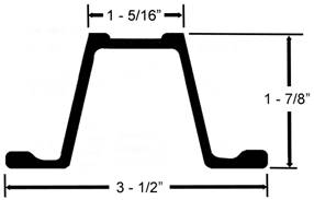
U Channel Posts Specification 2528.02 allows 3 pound per foot U Channel posts as one of the three post mounting options for work zone signs. An easy way to determine if the supplied post is a 3 pound per foot post, use the image at right and dimensions as a guide.
|
|
5.35 REMOVAL OF TEMPORARY PAVEMENT MARKINGS
Temporary pavement markings are necessary for most construction projects. Typical locations include runarounds, diversions, staged construction, etc. When temporary pavement markings are placed, they will eventually be removed as part of the project.
Removal depends on the type of pavement marking material placed and type of surface to which it is attached (new or old, HMA or PCC). Two types of temporary pavement markings are currently used: wet retroreflective removable tape markings and heavy metal free waterborne paint.
Pavement Marking Removal Characteristics
Each temporary pavement marking material has its own removal characteristics:
· Wet Retroreflective Removable Marking Tape
This material is precoated with pressure sensitive adhesive, adheres well under traffic, and also removes without a trace. This material does not require the need to place raised pavement markers to provide wet nighttime visibility. This is the only material available for use on diagonal lines per Specification 2527.02, D, 1. This material is the most expensive of the two temporary pavement markings
· Temporary Painted Pavement Markings
This material is the most commonly used material for temporary pavement marking due to its economical price. It requires removal according to Specification 2527.02, D, 2. Temporary painted pavement marking materials must satisfy requirements of Specifications 4183 and 4184.
· Removable, Non-reflective, Preformed Tape
In lieu of removing the existing permanent pavement markings, contractors may elect to cover them with removable, non-reflective, preformed tape. This material is designed to be applied over the existing markings and then can easily be removed from the pavement’s surface without damaging the underlying pavement markings. It is rather expensive, but it does have the advantage of not requiring removal, installation, and re-removal of a pavement marking to delineate the construction work zone.
Disposal of Removed Pavement Marking Materials
All pavement marking removal operations shall be completed in accordance with Specification 2527.03, C. This article requires that removal operations be essentially dust free and collect all of the removed product from the road surface. Disposal of this combined pavement surface and pavement marking material shall be according to appropriate federal and state regulations. Typical pavement marking removal operations consist of dry vacuum grinding, shot blasting, or water blasting. All removed pavement marking materials shall be disposed according to the following Iowa DNR requirements:
· Pavement marking waste (including water) may remain on the roadside (granular or earth shoulders and foreslopes) with the following exceptions, as long as it is removed from the pavement surface itself. The waste may not be discharged directly into a stream or storm sewer or where it would likely runoff into a waterway. Linear disposal of pavement marking waste along the roadside should not cause any noticeable build-up of waste material.
· On all bridges, and within 100 feet of bridges, pavement marking waste should be retained and may be released outside of these areas as long as the discharge does not cause a noticeable build-up of waste material or where it would likely runoff into a waterway. For these areas, pavement marking waste may also be collected and disposed at a permitted landfill.
· In areas with storm sewer drainage from the roadway, the pavement marking waste material must be collected. This collected waste must be disposed at a permitted landfill after all water in the waste, if any, has been decanted from the waste. Process water and decanted water must be disposed at a wastewater treatment facility.
5.36 CRASHWORTHY WORK ZONE DEVICES
NCHRP 350 (National Cooperative Highway Research Program 350) Report or Manual for Assessing Safety Hardware (MASH) is the national standard for crash testing work zone signs and devices. The FHWA, in a letter to the Department on August 28, 1998 mandates that all work zone signs and devices being used on the National Highway System be NCHRP 350 compliant. The letter divided the various types of signs and devices into four categories. The Department has determined that all work zone signs and devices used on the entire Department administered highway system be NCHRP 350 or MASH compliant. This DOES NOT include county roads or city streets. The Department is in the process of adopting MASH crashworthiness criteria to all work zone devices through updating approved product lists in MAPLE.
The four NCHRP 350 categories of work zone devices are defined as follows:
· Category 1 includes small and lightweight channelizing and delineating devices that have been in common use for many years and are known to be crashworthy by crash testing of similar devices or years of demonstrable safe performance. These include cones, tubular markers, flexible delineator posts, and plastic drums with no attachments.
· Category 2 includes devices that are not expected to produce significant vehicular velocity change but may otherwise be hazardous. Examples of this class are: barricades, portable sign supports, intrusion alarms, and drums, vertical panels, or cones with lights. Testing of devices in this category will be required. However, they may qualify for the reduced testing requirements.
· Category 3 is for hardware that is expected to cause significant velocity changes or other potentially harmful reactions to impacting vehicles. Hardware in this category must be tested to the full requirement of NCHRP 350. Barriers, fixed sign supports, crash cushions, and other work zone devices not meeting the definitions of Category 1 or 2 are examples from this category.
· Category 4 includes portable or trailer-mounted devices such as Arrow Displays, Temporary Traffic Signals, Area Lighting Supports, and Portable Dynamic Message Signs.
Specification requirements for NCHRP 350 compliant devices are found in Specification 2528.01, A sixth and seventh paragraphs. A list of FHWA approved NCHRP 350 and MASH compliant devices can be found through the Internet at:
Contractors have the responsibility to provide documentation to the administering RCE Office that all work zone signs and devices used on the contract are NCHRP 350 or MASH compliant. This documentation should be on contractor letterhead and shall include the vendor’s self-certification for Category I signs and devices and the FHWA “WZ-XX” acceptance memorandum for Category II signs and devices. A sample documentation letter is included in Appendix 5-4.
5.37 INSTALLATION & REMOVAL OF TRAFFIC CONTROL ZONES
Installation
Temporary traffic control devices are always installed in the direction that traffic flows...that is, "downstream." The first device placed on the roadway is the first advance warning sign; typically the "ROAD WORK AHEAD" sign. The installation then proceeds with the signs in the advance warning zone, continues through the transition zone into the actual work area, and finishes in the termination zone.
All vehicles used to carry the temporary traffic control devices need to be parked in a safe location such as on the shoulder, at a field entrance, parked legally at a marked parking stall, or on the curb line in urban areas. These vehicles should display their four way flashers and any amber flashing or rotating warning lights.
All semi-permanent or permanent traffic control zones should be reviewed prior to the actual installation time. This review should consist of "pre-marking" the location of all signs and devices. Pre-marking sign and device locations early should help to determine if corrections or modifications need to be made to the traffic control plan included in the contract documents. Any corrections necessary should be according to Construction Manual Section 5.22.
Removal
Temporary traffic control devices are always removed in the opposite direction that traffic flows...that is, "upstream." The first device removed on the roadway is the last sign; typically the "END ROAD WORK" sign. The removal then proceeds with the termination zone, continues through the actual work area, transition zone, and finishes with the advance warning zone and the “ROAD WORK AHEAD” sign.
5.38 SIGNALIZED VS. FLAGGER CONTROLLED EQUIPMENT CROSSINGS
The Design Bureau typically determines the need for haul road crossings during project design. These crossings are decided to be either a signalized or flagger controlled crossing based on factors such as economic analysis, safety concerns, and project uniformity. Occasionally, necessary haul road crossings are not included in the plans or field conditions are different from plan details and additional haul road crossings need to be added.
When haul road crossings are added in the field, RCE offices should review the flow chart in Appendix 5-7 to determine the appropriate haul road crossing to use. Questions pertaining to haul road crossings should be referred to the Construction and Materials Bureau.
5.39 TRAFFIC CONTROL EVALUATION REPORTING FORM
The Construction Traffic Control Process Improvement Team has developed the Traffic Control Evaluation Report (Form 830437) to help foster better communication between the contracting authority and the contractor regarding traffic control operation and effectiveness. A copy of this form is found in Appendix 5-10.
The intent of the form is to provide contractors with an easily understood evaluation during any point of time while a project is under construction. Use of this form should help modify a contractor’s performance by documenting the engineer’s concern during a project. As stated on the form, the use of this form and its distribution is solely between the engineer and contractor. Additional distribution is not needed.
Instructions for completing the form are shown on the backside of the form.
5.40 TRAFFIC QUALITY CONTROL
Specification 2528.01, C emphasizes the importance and need for direct contractor involvement in traffic control by requiring a Traffic Control Technician in trained status.
This trained individual is intended to be in responsible charge of all traffic control duties for the contractor. Other contractor staff may perform the specific Traffic Quality Control responsibilities including completion of the daily traffic control diary, but overall management of the contractor’s quality control program for traffic control shall be the responsibility of the trained traffic control technician. Agency staff should perform quality assurance traffic control checks on a random basis, including reviewing the daily traffic control diary. Contractors who fail to provide a trained traffic control technician or fail to provide the required daily documentation shall be price adjusted according to Construction Manual Section 2.53.F.
When traffic control problems arise on a project, the Contractor’s traffic control technician should be called for an on-site visit to review the traffic control issue(s) at hand. This individual is required to be in responsible oversight of the project’s traffic control and should be the primary contractor contact for project staff relating to traffic control issues on the project. Continued traffic control problems may require a written letter to the contractor requesting a review by the traffic control technician. Copies of any correspondence regarding traffic control issues should also be sent to the Construction and Materials Bureau.
One of the more critical responsibilities of the traffic control technician is to ensure that a daily traffic control diary is maintained. Specification 2528.01, C, 2 states that the daily traffic control diary shall be submitted to the Engineer in a format provided by the Contracting Authority. A sample format can be found in Appendix 5-11. The portion of the form that includes the listing of flaggers may be submitted as a separate document, as long as the Engineer receives it on a daily basis.
Entries in the traffic control diary should be made in ink. The daily traffic control diary becomes the property of the Contracting Authority upon completion of the project.
The interval which the diary needs to be submitted to the Engineer should be discussed at the preconstruction conference. A typical interval would be every two weeks for most projects.
Specification 2528.01, C, 3 requires that the workers who set up and remove temporary traffic control devices within the traveled way or median must be supervised by a trained traffic control technician and that the daily traffic control diary be signed by the trained traffic control technician. This language is intended for complete installations and removals and is not intended to be required when a worker moves or replaces individual devices or signs as part of routine daily maintenance. If the temporary traffic control is installed and removed each day, as in patching or resurfacing contracts, then naturally these workers need to be supervised by a trained traffic control technician and the daily traffic control diary needs to be signed by the trained traffic control technician.
5.41 ROAD CLOSED vs. ROAD CLOSED TO THRU TRAFFIC
|
The ROAD CLOSED sign (R11-2) should be used when the roadway is closed to all road users except contractors' equipment or officially authorized vehicles. No local traffic should need to use the road beyond the location of the sign. This sign should be accompanied by appropriate |
|
|
|
warning and detour signing and should be installed on a Type III barricade that physically closes the roadway and is included as part of a road closure per Specification Article 2518. The ROAD CLOSED sign shall not be used where road user flow is maintained or where the actual closure is some distance beyond the sign.
|
||
|
The ROAD CLOSED TO THRU TRAFFIC sign (R11-4) should be used where road users follow detours to avoid a closure some distance beyond the sign, but where local road users can use the roadway to the point of actual physical closure using a road closure |
|
|
|
per Specification Article 2518. Appropriate warning and detour signing should accompany these signs. Since the road is open to traffic, appropriate signs and warning devices should protect any work activity within the normal highway surface. Equipment parked within the normal highway surface should be protected by a minimum of a single Type III barricade or two drums on each side for approaching traffic. When public traffic is allowed on existing pavement or if public traffic is allowed on new pavement, any work area within a paved surface should include appropriate flagging procedures per Standard Road Plan TC-213 and according to Iowa DOT Flagger Training Materials. In addition, when public traffic is allowed on the new pavement any shoulder drop-offs should be protected by a shoulder closure per Standard Road Plan TC-202. |
||

5.42 TEMPORARY WORK ZONE SPEED LIMITS
The
Department’s policy regarding speed limits in temporary traffic control zones
is based on Part 6 of the MUTCD.
In general, attempts to reduce speeds increase the likelihood of accidents. Signing alone does not compel most motorists to drive at the posted speed limit. The few drivers who do slow down create a speed differential in the traffic stream and thus increase the likelihood of rear-end accidents. Drivers must perceive a reason to slow down. Some of these reasons include enforcement of the posted speed limit, work activity near the open lane, adverse weather conditions, and roadway geometry. To the extent possible, the Iowa Department of Transportation designs a temporary traffic control zone to accommodate the normal operating speed of traffic traveling on the roadway segment.
The most dangerous aspect of a temporary traffic control zone is not speed but inattentiveness. By making work areas more visible, drivers will be more alert to changing conditions and have time to respond appropriately. Signs, flaggers, and other traffic control devices alert motorists and guide them safely through the temporary traffic control zone. The safest traffic control zone is where everyone pays attention and travels at the same speed.
That said, it is not always possible to design temporary traffic control zones to accommodate the normal operating speed. Therefore the following guidelines are meant to provide uniformity when it is necessary to reduce speeds in temporary traffic control zones.
Regulatory Speed Limit Changes Necessary During Construction:
The contract documents shall include a temporary traffic control plan that adheres to the following guidelines:
Two Lane Highways:
· Maintain existing regulatory speed limit.
· Post appropriate advisory speeds. On-site detours should be designed as close to the existing speed limit as practical. Often available right of way and roadway geometry make it impractical to maintain the existing operating speed. At locations where lower design standards for vertical and horizontal alignment are necessary, temporary advisory speed signing informs motorists of the recommended safe speed.
Multi Lane Divided Highways:
Four Lane Divided Highways:
· Existing regulatory speed limit (65 mph, 60 mph, or 55 mph) maintained if all existing lanes are open to traffic and the width between barriers (other than spot locations) is 30’ or greater.
· Regulatory 55 mph speed limit where the roadway width between barriers is less than 30’ (TBR, 3’ shoulder, 12’ lane, 12’ lane, 3’ shoulder, TBR) other than spot locations such as bridges.
· Regulatory 55 mph speed limit with single lane closure only when workers are present
· Regulatory 55 mph speed limit where construction vehicles must frequently merge into high volume traffic lanes.
· Regulatory 55 mph speed limit with single lane closure using temporary barrier rail due to potential side friction from use of barrier rail
· Regulatory 55 mph speed limit for two-lane, two-way operation (TLTWO).
Six Lane or More Divided Highways:
· Existing regulatory speed limit (65 mph, 60 mph, or 55 mph) maintained if all existing lanes are open to traffic.
· Existing regulatory speed limit (65 mph, 60 mph, or 55 mph) maintained if at least two existing lanes are open to traffic per direction and the cross section configuration is 30’ or greater.
· Regulatory 55 mph speed limit when cross section configuration is less than 30’ (TBR, 3’ shoulder, 12’ lane, 12’ lane, 3’ shoulder, TBR)
· Regulatory 55 mph speed limit with only single lane available to traffic
Procedure for Changing Regulatory Speed Limit
If field conditions warrant a reduced regulatory speed limit not contained in the plans for an active construction project, the following steps shall be used to obtain a Staff Action concurrence. A Staff Action is necessary to provide legal backing for the requested speed limit change.
1. The Resident Construction Engineer, after consultation with the District Construction Engineer, will contact the Construction and Materials Bureau to review the request for statewide uniformity using appropriate engineering judgment.
2. Electronically submit to the Construction and Materials Bureau the following information for the proposed speed limit Staff Action:
· Project Number and project type
· County
· Proposed location of reduced regulatory speed limit signs
· Calendar duration of the proposed reduced regulatory speed limit
· Discussion of reasons for reduced regulatory speed limit
· Timeframe required to obtain approval of Staff Action
3. The Construction and Materials Bureau will forward its comments and concurrence along with the above information to the Traffic and Safety Bureau.
4. The Traffic and Safety Bureau will prepare and track the Staff Action
Upon approval the Traffic and Safety Bureau will forward a copy of the Staff Action to the Construction and Materials Bureau and the appropriate RCE and DCE Offices.
5.43 FLAGGER AND WORKER SAFETY APPAREL (ANSI 107)
Refer to the Iowa DOT Flagger Training Materials and Specifications 2528.03, O, 3 for detailed worker safety apparel requirements.
These standards provide a uniform, authoritative guide for the design, performance specifications, and use of high-visibility apparel including vests, jackets, bib/jumpsuit coveralls, pants and harnesses. Garments that meet these standards can be worn 24 hours a day to provide users with a high level of conspicuity through the use of combined fluorescent and retroreflective materials.
5.44 MONITORING OF TRANSPORTATION MANAGEMENT PLANS FOR SIGNIFICANT PROJECTS
Projects on high volume roadways that involve lane restrictions can result in undesirable delay and inconvenience to road users. The Federal Highway Administration has adopted a rule on work zone safety and mobility that applies to certain Iowa DOT projects, which are defined as “significant projects”. For projects designated as significant in the contract documents, additional responsibilities may need to be undertaken by the contractor and resident construction engineer. These projects will include a special provision that outlines these responsibilities.
All projects let by the Iowa DOT require a Transportation Management Plan (TMP). For most projects the TMP will consist of only a Temporary Traffic Control (TTC) plan. Other projects may also include elements relating to Transportation Operations (TO) and Public Information (PI). Significant projects however will require the development, implementation, and monitoring of a complete TMP with the intent of minimizing impacts on traffic mobility and convenience, while providing maximum safety for workers and road users. A complete description of the Iowa DOT program for accommodating safety and mobility in work zones can be found in Iowa DOT Policies and Procedures Manual 500.18.
Monitoring the TMP at the Project Level
For projects designated as significant, a team will develop details of the TMP and a manager will be selected to provide oversight for implementation of the TMP at the project level. Included in the implementation plan may be verification of temporary traffic control, assessment of TMP performance considering such factors as queue length, traffic delay times, public complaints, etc., tracking of implementation costs, documentation of revisions and corrective action, and designation of responsibilities for each task.
Following the award of contract, administration and monitoring of a significant project TMP will become the responsibility of the resident construction engineer with oversight provided by the District TMP manager.
Duties of the resident construction engineer as stated in the project specific special provision may include some of the following, depending on the specific project requirements:
· Carefully review and be familiar with the details of the TMP in the contract documents
· Assign TMP monitoring responsibilities to trained inspection staff.
· Review TMP details and responsibilities with the contractor at the pre-construction conference
· Record contact information for the contractor’s trained representative with TMP monitoring responsibilities
· Maintain close liaison with the contractor to assure compliance with TMP provisions and assure that traffic restrictions, especially lane closures, are promptly removed when not needed.
· Review the need for and request law enforcement officers to provide for extra enforcement for the project.
· Document the use of extra enforcement, including costs, impacts, and opinions of effectiveness.
· Review the need for public information dissemination, and provide timely news releases, and consider the use of changeable message signs.
· Document public information activities.
· Document any approved revisions to the TMP
· Maintain a log of performance related issues for the TMP, such as incident response, extraordinary delays and long queues, and complaints from the public.
· Record and maintain a detailed description of crashes that occur in the work zone in compliance with Construction Manual Section 5.23
· Assist the TMP manager in preparation of a final TMP effectiveness report at the completion of the project.
Duties of the contractor relating to significant projects will also be included in the same special provision. It is the responsibility of the resident construction engineer to assure that these duties are completed in a satisfactory manner.
5.45 EXTRA ENFORCEMENT GUIDELINES FOR CONSTRUCTION PROJECTS
The use of Extra Enforcement (paid law enforcement) on Iowa DOT construction projects is encouraged for high volume projects and / or those with high complexity where the driver may be confused. These guidelines have been developed to promote uniformity in the planning, operation, and payment for extra enforcement. The document can be found in the Work Zone Reference Library: https://iowadot.gov/workzonereferencelibrary
5.46 VEHICLE WARNING LIGHTS
Specification 2528.03, O, 11 requires all Contactor vehicles to display an operating amber or yellow cab mounted warning light. This requirement includes private employee vehicles entering or existing the work area. If this light is not present or not correctly functioning the Contractor has 24 hours to install or repair or replace the light after being information by the inspection staff. After the 24-hour time period has elapsed, the Contractor may be charged a traffic control related price adjustment per Construction Manual Section 2.53.F.
5.47 LANE SHIFTS WITHIN WORK AREAS
The policy of the Department is to allow for lane closures on both two-lane roadways and multilane highways to provide a work area for our Contractors. These lane closure traffic control requirements are shown in various Traffic Control Standard Road Plans, such as TC-214 for two-lane roadways and TC-418 for multilane highways. These Traffic Control Standard Road Plans show public traffic traveling in the same single lane or same multiple lanes as they pass the active Contractor work area. The Department does NOT allow traffic traveling past a work area to move from one lane to another via a shift due to the potential confusion of the motorist as to what is their proper lane of travel and to keep them from incorrectly traveling in the closed lane which is reserved for the Contractor’s use. If a Contractor needs to shift traffic from one lane to another, then an individual lane closure spaced per the requirements of Specification 2528.03, M, 9 should be used to close each lane.